A Latching relay works electrically like a normal
relay, though it maintains its position even after power has been removed. This
means that it'll keep in either the “rest” or “set” position till consequent
input of power. This allows it to own a basic memory attribute.
An example of a latching relay would be once
multiple light switches control one light. The relay can need to remember what
position it had been in so that it will properly flip the light on or off. If
the relay had not “latched”, the light switch wouldn't be within the correct
position to vary the light’s standing.
A latching relay is a relay that solely attracts
power throughout the brief voltage pulse required to create it changes state.
These are very useful in situations where energy efficiency is important, but
also in situations where you need the relay to remember its state – typically
so that the user will press a button to shut the relay and press a second
button to open the relay once more. The relay remembers which button was
pressed last.
Latching relays can be high-ticket, notably after
they are needed to change high currents – so wherever energy potency isn't
important, but relay latching is required, it is possible to use the circuit
design that follows to create a non
latching relay using a lavatory commonplace DPST or DPDT relay.
Make a
Latching Relay
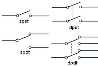
DPST (double pole single throw) and DPDT (double
pole double throw) relays are relays which have two switches – i.e. they can
control two different things at the same time.
The diagram above shows, however, such a relay will
be wont to build a latching relay circuit. The circuit has 2 buttons – one may
be a push to create that closes once ironed but is otherwise open, and the
other is a push to break which opens when pressed but is otherwise closed. When
the push to make button is pressed, 12V goes across the coil energizing the
relay. This closes the 2 internal relay switches connecting A to B, and C to D. A connected to B, the positive from the 12V power source feeds through A
and B to arrive at the relay coil keeping it energized even when the push to
make button is released. Therefore the relay has been latched.
In order to de-energize the relay, the push to
break button needs to be pressed which cuts the positive connection feeding
through A and B and energizing the coil. With that button pressed, there is no
voltage across the relay coil and so it re-energizes.
While the relay is latched, C and D are connected
and therefore can be used to switch on whatever device or appliance is to be
controlled by this latching relay system.
Push to make and push to interrupt buttons are available
cheaply here: push buttons during a range of colors, as shown higher than, to
offer clear visual differentiation between the latch on and latch off button.
An electromechanical non
latching relay is an electrical switching Latching Relay device. Its
operate corresponds to a mechanical switch, that is electrically motivated. A:
It is a relay that is set (ON) or reset (OFF) by the input of a pulse voltage.
Latching Relays. In these Relays, the set input pulse causes the operative condition.
An electrical system is to use relays that do not require constant power to the
circuit. Latching relays also are fascinating once the client must have a
relay.


Comments
Post a Comment